|

|
|
|
|
H.B.S Trading LTD. |
|
|
|
Pressure |
Regulators |
|
|
|
|
|
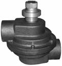
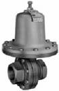
Low Flow Pressure
Regulator JPR/JHR |
|
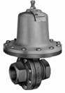
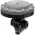
Low Flow Pressure
Regulator JHP |
|
|
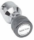 |
The JPR and JHR
pressure reducing |
|
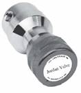 |
The JHP is designed
for gases and |
|
|
regulators are
designed for gas or |
|
liquids with inlet pressure
to 3600 psig |
|
liquid service and with
inlet pressures |
|
Standard adjustable
outlet ranges |
|
|
up to 3600 psi (248 bar). Standard |
|
from 50 - 1500
psig. Flow coefficient |
|
|
adjuststable
outlet ranges are from |
|
of 0.06. This
general purpose use |
|
|
1 - 10 psig (0,07
-0,69 Barg) thru |
|
regulator can be
ordered with a |
|
|
10 - 750 psig (0,69 - 51,7 Barg). The |
|
variety of options to
meet your |
|
|
JPR/JHR Series can be
manufactured |
|
system demands. |
|
|
from various barstock materials |
|
Panel or surface mounting |
|
|
|
|
|
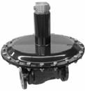
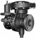
Low Flow Back Pressure
Regulator JBP |
|
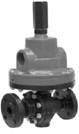
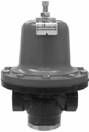
Cylinder Pressure
Regulators JCYL/JCYL-2 |
|
|
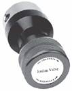 |
The JBP back
pressure regulator is |
|
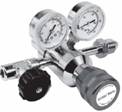 |
The JCYL Cylinder Pressure
Regulator |
|
designed for
gas or liquid service up |
|
and JYCL-2 Two Stage
Cylinder |
|
|
to 750 psig. Flow
coefficients are |
|
Pressure Regulator are designed |
|
|
available in 0.10, 0.20 and 0.30. The |
|
for gas or
liquid service with inlet |
|
|
back pressure
regulator controls the |
|
pressures up to
3600psig. Standard |
|
|
inlet
pressure. It is used to maintain a |
|
adjustment outlet ranges from |
|
|
pressure in a process, or act in a |
|
1 - 10 psig thru 10 - 750 psig . |
|
|
relief valve
capacity. It can be |
|
The JCYL is designed to handle |
|
|
manufactured in a variety materials. |
|
Line Sizes: Standard — 1/4" (DN8) |
|
|
|
Flow Regulators Mark 130 |
|
Self-Operated Back
Pressure Regulators |
|
|
 |
1/4" through 2" (DN8 through DN50) |
|
 |
Mark 50 |
|
|
The Mark 130 is
a flow regulator that |
|
1/4” & 3/8”
sizes use 1/2” body |
|
|
will maintain a
constant downstream |
|
The Mark 50 is used
to regulate |
|
|
flow rate regardless of inlet or outlet |
|
upstream pressure at a
predetermined |
|
pressure fluctuations. |
|
setpoint. The
spring in the Mark 50 |
|
|
1/4"NPT 0.1-1 GPM & 0.05 - 0.5 GPM |
|
holds the
sliding gate seats in their |
|
|
1/2"NPT 1 to 10 GPM & 0.5 to 5.0 GPM |
|
normally closed position. |
|
|
3/4"NPT 2-20 GPM; 1" NPT 3-30 GPM |
|
high pressure
setpoints up to 450 psi |
|
|
1-1/2"NPT 7-70GPM; 2"NPT 8-90 GPM |
|
(31,03 bar) |
|
|
|
GAS BACK PRESSURE
REGULATOR MK508 |
|
Differential Back
Pressure Regulators Mark 53/54 |
|
 |
Line Sizes: 1-1/2” (DN40), 2” (DN50) |
|
 |
1/4”(DN8)&3/8”(DN12)use 1/2”(DN15) |
|
|
The MK508 vents gas from the
tank to |
|
The Mark 53
maintains a constant |
|
|
prevent blanketing
pressure from |
|
differential between the
inlet pressure |
|
rising to a level that could
damage the |
|
and the pressure loaded on top
of the |
|
tank. Inlet pressures up to 25 psi . |
|
diaphragm. |
|
|
Rugged, heavy-duty design
— |
|
Straight-through
flow for reduced |
|
|
emergency outlet
pressure may |
|
turbulence and quiet operation; |
|
|
reach 100% of inlet pressure
without |
|
Short stroke for
fast response and |
|
|
damaging valve |
|
accurate regulation. |
|
|
|
|
Vacuum Regulators Mark 55 |
|
Air Loaded Back Pressure
Regulators Mark 56 |
|
|
 |
1/2” (DN15) through 2” (DN50) |
|
 |
1/2” through 6”(DN15 through DN150) |
|
|
Vacuum Control Ranges: |
|
The operation of
the MK56 requires |
|
|
1” Hg to 25” Hg vacuum. |
|
no control
spring or pilot. Instead, a |
|
|
They are used to
maintain vacuums |
|
static air signal is applied to the top of |
|
|
at predetermined
settings and to |
|
the diaphragm to
determine the |
|
|
regulate vacuums on
evaporators, |
|
setpoint. |
|
|
cookers,grinding
fixtures, milking |
|
Max ∆P 325 PCI --
2" DN50 |
|
|
machines, altitude
chambers and |
|
Max ∆P 150 PCI --
6" DN50 |
|
|
other vacuum systems. |
|
Max ∆P 550 PCI --
1/2" DN50 |
|
|
|
Externally Piloted Back
Pressure Regulators |
|
Cage Trim Back Pressure
Regulators Mark 58 |
|
|
 |
Mark 57 |
|
 |
1/4" through 2" (DN8 through DN50) |
|
|
The inlet pressure passes
through the |
|
Maximum Inlet Pressure: 300 psi . |
|
|
inlet pilot
tubing beneath the pilot |
|
Maximum
Temperatures:350°F with |
|
|
diaphragm. When the setpoint is |
|
Viton seats and Viton or SST |
|
|
reached, the
force of the adjusting |
|
diaphragm. |
|
|
spring is overcome and the
pilot valve |
|
Minimum Temperatures: -20°F
(-29°C) |
|
opens. |
|
with Buna-N seats and diaphragm |
|
|
1/2” (DN15) through 6” (DN150) |
|
ANSI Flanges — 150#, 300# |
|
|
Max ∆P 325 PCI --
6" DN50 |
|
DIN Flanges — PN10/16, PN25/40 |
|
|
|
|
|
|
|
|
|